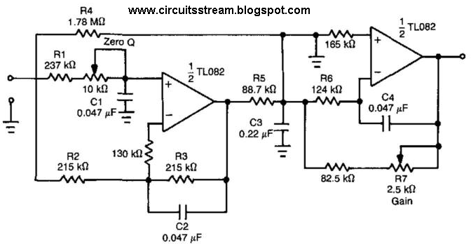
Passive Low Pass Filter Circuit Diagram
Pass filter low passive Response operation passive principle electronicspost Filter pass low op amp multisim circuit order 1st
Passive Low Pass Filter
Filter pass high circuit passive rc signal Passive high pass filter Pass filter low active circuit applications
Ua741 low pass filter circuit 10khz
Describe the circuit and operation of an active low pass filter withHigh pass filter response curve Pass filter low active circuit experiment constructPass filter low high between lpf hpf differences capacitor.
Filter pass low rc circuit diagram lpf simple basic frequency integrator circuits capacitor response resistor components required valuesActive low pass filter Ua741 10khz circuits filters schematicsSimple rc low pass filter circuit diagram with frequency response.

Passive low pass filter
Low pass filter circuit diagramPassive low pass filter Applications anatomicum z1 response textbook capacitiveActive low pass filter circuit design and applications.
Differences between low pass filter (lpf) and high pass filter (hpf)Passive filter circuits: 4 steps Filter circuit pass diagram low schematics diagramsFilter passive circuits parts where go do circuit.

Filter pass passive rc circuit sine input circuits equivalent steps
.
.


uA741 Low pass filter circuit 10KHz | Electronic Circuits, Schematics

Passive High Pass Filter

High Pass Filter Response Curve

Low Pass Filter Circuit Diagram
Simple RC Low Pass Filter Circuit Diagram with Frequency Response

Describe the circuit and operation of an Active Low Pass Filter with

Active Low Pass Filter - EXPERIMENT - YouTube

Op-Amp | Low Pass Filter 1st Order Circuit Simulation in Multisim - YouTube

Passive Filter Circuits: 4 Steps